Relative Facilities, Canvas, and You
January 7, 2020 /
0 comments / in
/ by Blake Miller
Relative facilities have been around in CygNet in some shape or form for many years. And along the way, there were enhancements made to Studio to assist in creating multi-facility templated screens based on a relative linking model. However, with Canvas, that relative linking functionality and resolution was baked into the product at the very beginning. In this post, I’m going to discuss some design considerations and implementation ideas that I hope will help as you create Canvas screens.
Background
The relative facility model used by Canvas and in the CygNet .NET API is based on a linking technique and facility filters. Facility filters are used throughout the CygNet application to obtain a list of facilities that satisfy a given criterion. For example, a filter of “facility_type=‘GASMTR’” would return a list of all gas meters for a given Facility service.
However, in the case of relative facilities, we are asking a different question. We don’t want to know about all facilities; we want to know about a single facility. For example, we want to know about the gas meter facility associated with a specific well. We can get at this association by expanding the facility filter rule definition. For example, a filter of
“facility_type=‘GASMTR’ AND facility_attr3=‘SITE.UIS::ASH_WL’”
would produce the gas meter facility that is linked to the ‘SITE.UIS::ASH_WL’ facility. If this filter does not produce a single facility, then additional filter attributes are needed to ensure that a single facility resolution occurs. Here we are using facility_attr3 as the means to “link” two facilities. In this case the ASH_GM facility would have ‘SITE.UIS::ASH_WL’ as a value for facility_attr3.
This example highlights the first rule of relative facility resolution. Resolution must result in a single facility. Otherwise, if we try to build an Ash Well screen to show the gas rate of the well, how do we know which facility to use if we return more than one resolved facility?
Relative Facility Definitions
Paths between relative facility definitions are automatically created during configuration. These represent the route the relative facility model will use to resolve the links in the facility chain.
Consider the following example:
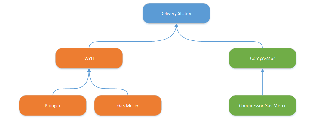
Here, paths are created from every definition to every other definition in the chain. For reference, the following table shows the paths created for the Well relative facility definition shown in the example above.
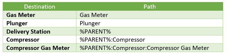
So, to resolve to the Compressor Gas Meter for a given Well facility, we will resolve each of the individual links in the chain. We first resolve the Well’s parent facility. Then we use that facility to resolve the Compressor facility. Once we have the Compressor facility, we resolve the Compressor Gas Meter facility.
These resolutions can occur because each link in the chain resolves to a single facility and each definition is unique. This represents the second rule of relative facilities. Relative facility definitions can only be linked once, that is, each facility can only have one parent.
Order-in-Type Definition and Multi-Parent Facilities
Consider this modification to our example:
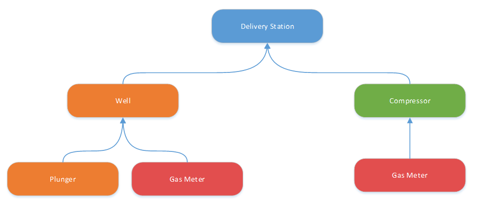
Here we have the same definition, Gas Meter, linked to both the Well and Compressor definitions. So, if we were to build a Plunger screen and wanted to show the Gas Meter on it, which Gas Meter definition will be used? Which one do you want to show? This conundrum represents the multi-parent problem. And this problem is exacerbated when you have Order-in-Type-based definitions.
Here is an example of that.
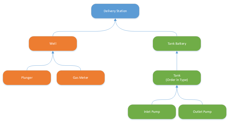
In this example we have an Order-in-Type-based definition for Tank, which is the parent of two other definitions, Inlet Pump and Outlet Pump. Since there could be more than one Tank in the chain, then the Inlet Pump and Outlet Pump definitions could have multiple parents. This configuration will create challenges for representing all this data on a single screen.
In order to build these definitions without creating a multi-parent configuration, you currently have to create a definition for each Tank (i.e., Tank 1, Tank 2, Tank 3, Tank 4, etc.). Then for each Tank you would need definitions for the Inlet Pump and Outlet Pump (i.e., Tank 1 – Inlet Pump, Tank 1 – Outlet Pump, Tank 2 – Inlet Pump, Tank 2 – Outlet Pump). You can quickly see how many definitions would be required to support a large number of Tanks with only two child definitions for each. This could create an administrative and maintenance challenge.
For this reason, the Relative Facility Definitions configuration dialog within Canvas does allow you to create these multi-parent configurations. However, in order to avoid resolution issues with these configurations we need to employ some clever design techniques when building screens. Also, in the upcoming 9.4 version of Canvas, we have added the ability to create a single definition for this situation and specify the order-in-type attribute.
A Special Case
There is a special case when resolving relative facilities. To illustrate this, consider this simplified configuration:
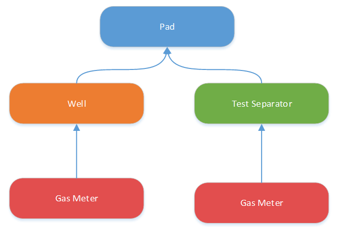
Here we have the same definition for Gas Meter, linked to a Well definition and to a Test Separator definition. If we build a Well-based screen and add a control using the relative facility link ‘Gas Meter’, it will resolve to the Gas Meter definition linked directly to the Well definition. If we switched the screen's facility to a ‘Test Separator’ facility, the control would resolve to the Gas Meter definition linked to the Test Separator definition.
The special case is that if there is a direct link between the definitions, then that link will be used. Thus, a Well can resolve directly to its Gas Meter without issue. Similarly, a Test Separator can resolve directly to its Gas Meter without issue. We just cannot go outside of those direct links for the facility resolution.
A Solution
With this in mind, we can use some special Canvas controls to help us build a screen that will resolve facilities in the way we want.
Consider the following Canvas screen:
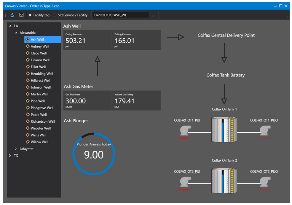
Here the screen’s facility is driven by the Tag Chooser control on the left. The top most set of Detail controls next to the Tag Chooser are related to the Well. These controls are configured to use the screen’s facility. The two sets of controls below the Well, the Gas Meter Detail controls and the Plunger Donut control, are configured to resolve the screen’s facility tag using either the Gas Meter or Plunger definitions. The same is true for the Central Delivery Point and Tank Battery Text Tools on the upper right.
The challenging part of the screen is with facility resolution for the Tank 1 and Tank 2 controls on the lower right. The Tank definition is configured for Order-in-Type. And as such the Inlet Pump and Outlet Pump definitions have multiple parents. So, we cannot have controls representing the Inlet Pump or Outlet Pump directly on the screen. To solve the issue, we are using a Canvas Object on the screen to handle the facility resolution.
In Design mode the Canvas Object looks like this:
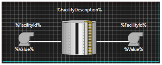
Here the two controls in the center depicting the tank level (a vertical Linear Gauge control overlaid on a tank Image) and the facility description (a Text Tool) are configured to use the screen’s facility. The Inlet Pump and Outlet Pump controls (Text Tools (depicting facility ID and value) and an Image) are configured to resolve the screen’s facility to either the Inlet Pump or Outlet Pump relative facility definition. This Object will use the special case in the relative facility resolution from above to resolve to the right facility.
On the main Canvas screen above, we are using two Object Viewer controls. The first Object (Tank 1) is configured to resolve the screen’s facility to the first Tank and the second Object (Tank 2) is configured to resolve the screen’s facility to the second Tank. We also could have used an Object Container control to show all Tanks without having to call out each one individually.
The technique used here is to split up the relative facility resolution in the event you have a multi-parent situation. In this example we had that at the Tank and Inlet Pump/Outlet Pump level. If there were further multi-parent configurations after the pump, you use the same technique there by creating additional Canvas Objects.
Since order-in-type definitions are new in 9.4, you can still use this technique but we have to modify the facility definitions slightly. Instead of having a single defintion for Tank (using the order-in-type field), you would create a definition for Tank 1, Tank 2, Tank 3, etc... Then for each of those defintions, you would link the Inlet and Outlet pump defintions. You will still have mulitple Tank definitions but you don't have to create individaul Inlet and Outlet pump definitions for each of those Tanks.
The use of the various Object-based Canvas controls helps us reuse screen components reducing long-term screen maintenance.
Summary
The built in relative facility functionality in Canvas allows us to create multi-facility templated screens right out of box. Just keep these few things in mind when building your relative facility definitions.
- Relative facility definitions represent the route that Canvas uses to resolve the links in a facility chain.
- Relative facility resolution must result in a single facility. When defining the filter for a definition, ensure that enough facility attributes are used to ensure a single facility is returned.
- Order-in-type definitions (a 9.4 feature) allow for multiple child facilities of a certain type by defining a facility attribute to specify an order-in-type value (the facility ordinal). Order-in-type definitions that have children inherently create multi-parent paths, which cannot be resolved on a Canvas screen.
- Multi-parent paths are created when a relative facility definition is used as a child link more than once. This creates a challenge to display these relationships when building Canvas screens. In these situations, create a Canvas Object that represents a single instance, for example, make an individual Tank Object with controls that are directly connected to the Tank relative facility definition. Then use the Object Viewer or Object Container controls to display the Canvas Objects on your screen.
Share this entry