Real Results

Performance By The Numbers

GuideWave® Tool, SineWave® Microimager

Determined Proper Well Placement, Detailed Reservoir Characterization for Multi-Stage Fracturing

Objectives

  • Identify natural fractures, acquire structural dip, and determine the fault location and its orientation.
  • Determine an optimal well path in a highly fractured zone using a combination of LWD measurements including deep azimuthal resistivity with boundary mapping inversion, nuclear density, neutron porosity, and micro-resistivity imaging.

Our Approach

  • The well was located in an area with a high geological uncertainty of sub-seismic faults and formation dip changes with lateral thickness variation changes.
  • The Weatherford Interpretation and Evaluation Services (IES) team suggested a logging-while-drilling (LWD) bottomhole assembly (BHA) with the distance-to-bed inversion combined with the azimuthal density images to fulfill the challenge of locating the target zone boundaries and formation dipping.
  • Weatherford experts conducted the preliminary analysis of the synthetics using the GuideWave azimuthal resistivity tools response model and developed an additional geological risk assessment and the drilling strategy.
  • Field personnel discussed the LWD results with the experts located in the Real-Time Operations Centre (RTOC) and agreed on the data required in real time for optimum data points per feet and the data that would be needed through the WITSML for the inversion.
  • The Weatherford team presented the customer with the geosteering model and discussed the geological uncertainties and identified the associated potential risks.
  • Micro-resistivity imaging, recorded while drilling and processed after the tools reached the surface, helped to detect clear geological features, especially fractures and faults, as well as the position.

Value to Customer

  • The combination of the density and distance-to-bed boundary tools with the inversion calculation provided critical formation data to establish proactive decision-making which helped to re-enter the target after hitting 31 ft (9.4 m) thrown down fault and continued drilling in the middle of the target.
  • The micro-resistivity image recorded while drilling helped to identify the fractured zones with high production potential.
  • The single-trip operation minimized rig time and costs by avoiding the sidetrack and running the micro-resistivity image tool in the same run for further identifying the natural fractures and faults which support the completion plan.
Details

Location

West Kuwait

Well Type

Oil producer

Formation

Mishrif (Carbonate reservoir)

Hole Size and Angle

6-1/8 in., 89.5°

Depth

6,477 to 8,352 ft (1,974.2 to 2,545.7 m)

Products/Services

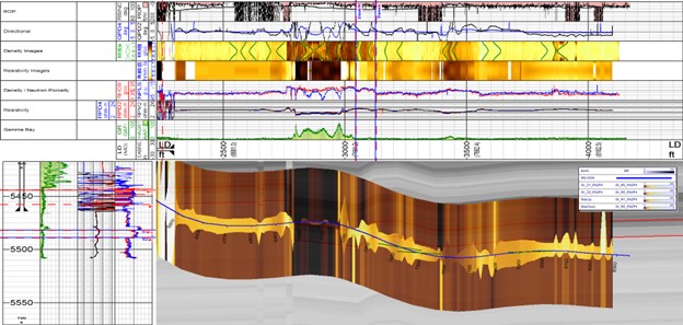
Final well placement earth model showing the entire well trajectory horizontal view for the lateral section with the faulted area.
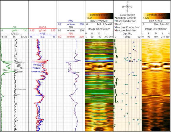
Micro-resistivity image plot showing geological features encountered.

Contact Weatherford

Take the next step in realizing the field of the future. Submit your details and one of our optimization experts will be in touch.